 |
 |
 |
|
It's simple to customize the Sentry to work in your particular plant.
It all starts at the touchscreen display - much like the ATM that everyone is familiar with.
The Main Screen, as shown below, provides the operator with just four settings.
- Sensitivity - do you want the probes to react to the slightest solids or do you want them to ignore the slightest solids?
- Probe Delay - should the Sentry wait for a period of time before sending an alert?
- Trigger - this is a refinement of the Probe Delay and represents the upper threshold of the event qualifier.
- Maintenance - this puts the unit on hold while the probes are cleaned so that an event is not triggered. It also counts the number of days since the last maintenance.
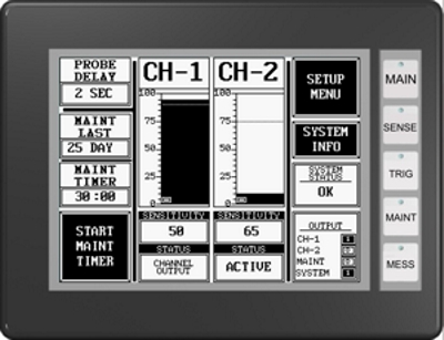
Above, MAIN Screen - This is the screen that is typically displayed
during system operation and is the start-up screen upon initial
power-up. Screen remains illuminated and active at all times. After
SETUP, this should be the only screen needed. CH1 and CH2 represents
a data group column and includes a channel meter, sensitivity window
and status window grouped for each channel. Each channel is
associated with an individual probe.
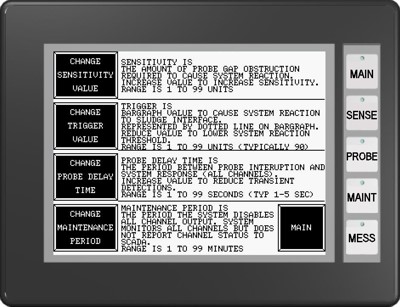
Above, SETUP Screen - Starting point for system parameter
configuration. Only four parameters are required to control the system;
Sensitivity, Trigger, Probe Delay, and Maintenance. Use these
parameters to customize the system that best suits your environment.
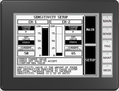
Above, SENSITIVITY Screen - Sensitivity values are independent
and my be different for all channels. Typically when all channels
are used in the same tank, channel-1 is the lower sensor probe
and monitors for initial sludge blanket contact. The second
channel probe is at a higher elevation. Adjust sensitivity for
each probe channel to provide sufficient notification of a rising
blanket.
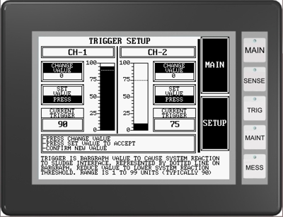
Above, TRIGGER Screen - Trigger values are independent and may
have different values for each channel. Trigger acts to hasten the
recognition of a rising sludge level.
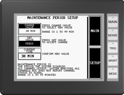
Above, MAINTENANCE Screen - The Maintenance time out value
is set on this screen. This is the amount of time that the probes
will be disabled for probe maintenance.
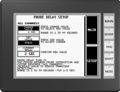
Above, PROBE DELAY Screen - adjusts the timed pause between
probe event detection and system reaction. A single value is
entered to affect all channels. This feature serves to preserve
the system and prevent spurious reactions to transient solids.
|
|
|
 |
|
 |
|